©2010-2026 All Rights Reserved


Your Emerging AECO Technology and Process Partners
Education - Selection - Implementation |
|
||||


|
|||||
|
|||||
As-built drawings for buildings that have been involved in remodels and additions often do not accurately reflect the most recent changes. Having to use these documents as the starting point for new designs can often result in the necessity to make changes during construction as errors become apparent to the field crews. These changes frequently cause delays, are costly to resolve, hamper attempts to prefabricate materials, and tie up available funds in large contingencies.
Industry studies have calculated that each Request for Information resulting in a Change Order costs on average $2,500 to resolve, plus any possible delays to the completion of the schedule. Waiting to discover structural, mechanical, equipment and architectural conflicts can easily result in tens or hundreds of unnecessary change orders. They may also result in field modifications that may not be the most efficient solution to a problem.
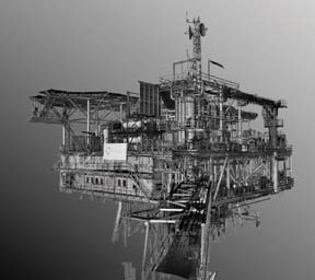
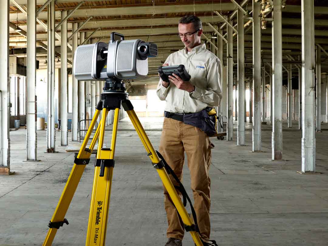
Aspenhills Consulting uses a Trimble CX 3D Laser Scanner to capture a point cloud of hundreds of thousands or millions of data points at the rate of 54,000 points per second and a range of 80 meters to accurately capture the size, configuration and location of objects. The WAVEPULSE technology combines the low-noise sensitivity and high distance discrimination of time-of-flight technology with the high, short-range accuracy of phase shift technology.
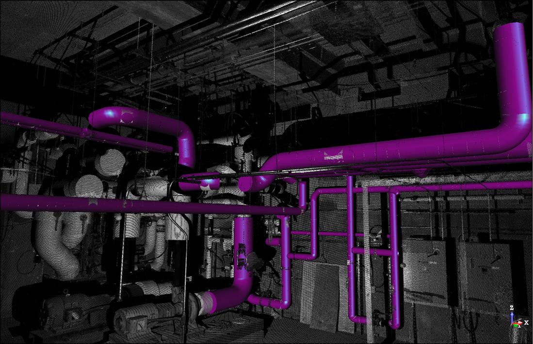
Our team will work with you to determine the required deliverable that best serves project requirements. Scans can be used to visualize either phased demolition and construction, or single view models, both useful tools for preparation of subcontracting quotes, planning work sequence, and project scheduling.
Scans are also valuable to model selective areas of new construction for quality control purposes or to verify dimensions prior to prefabrication of future building components.
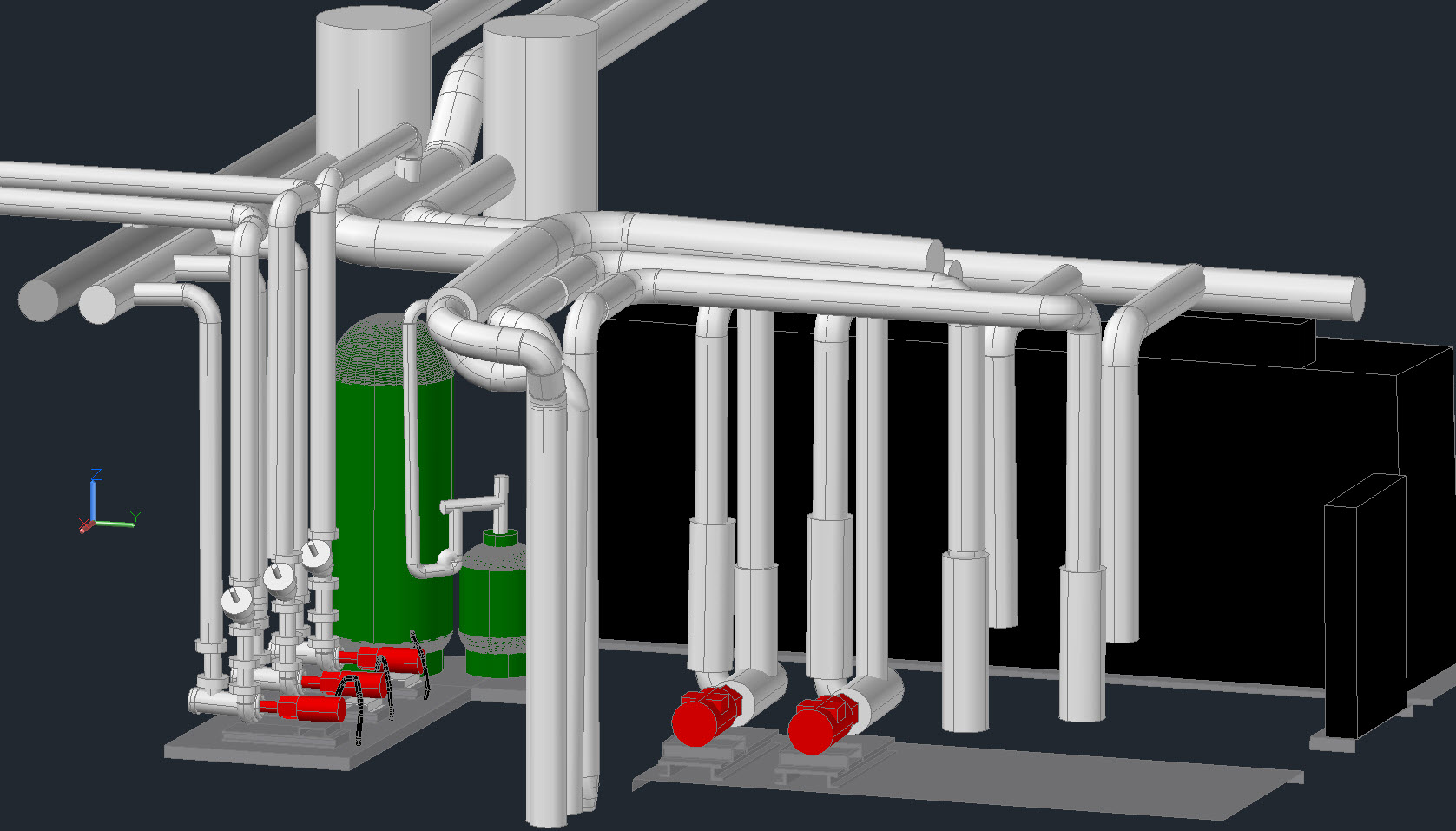
The output solid shapes model is viewable as a 3D DWG file format that is usable in all standard industry design software including; AutoCAD, Revit, ArchiCAD, Tekla, NavisWorks as primary programs; and viewable in a number of MEP specialty programs such as CADduct, CADPIPE, QuickPen.